Designing a FSAE Battery Pack
I was the electric powertrain lead on RIT's FSAE team this year and part of my job was designing the battery pack for our electric race car. The hardest part of this design was the tradeoffs between different cells, mechanical constraints, and electrical constraints. Luckily myself and the other people on the electric powertrain team learned a lot from our previous batter back designs and we were able to make some major improvements to this design.


The battery pack we designed for our latest car, F30
The battery pack is split into segments that can be easily disconnected without tools. This allows us to work on the batteries at safer voltages (~60v) rather than the full pack voltage of 300V+.

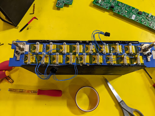
One segment of our battery pack without our custom BMS board attached
I worked on the segment design and electronics layout for this battery pack, and one of my teammates worked on the rest of the design. The design of the segment went smoothly; so far we haven't run into any major issues in our initial testing.
A major challenge when designing the segment was finding an insulated structural material that could hold all the cells in place without shorting them together. We ended up using machinable garolite (blue piece in the picture above).

Left: blank PCB I designed in Altium that acts as a mechanical component. Making it a circuit board was cheap and significantly easier to manufacture machining plates in house
Right: wave disc spring used to compress all the cells in the segment to increase their lifespan and rigidly mount them into the segment box
The largest manufacturing challenge turned out to be the 3d printed segment boxes that go around all the cells. They were just small enough to fit on our CR-10s when I added chamfers to the corners, but I had to manually override the printer dimensions in Cura to get it to generate gcode. I also ran into a lot of problems with the printer under extruding at the start of layers, which was pretty significant since the external walls are only two nozzle widths thick to act as an insulator. I got around this with some clever geometry inside the part to trick Cura into starting layers in different spots.

3d printed segment box with brass heat set threaded inserts

Cross section of the segment box with the pouch cells inside
Another unexpected challenge to overcome was the tolerance stackup of the cells. Each cell we purchased could vary in thickness by a fraction of a millimeter, but over all 36 cells in the segment this adds up to quite a bit. The solution I found was to model the cells far apart at the upper end of their tolerance, and then put insulating fish paper in between cells as needed to space them out evenly so they fit in the segment box properly. We also covered every other cell in Kapton tape; on a previous battery pack we ran into issues with parasitic discharge through the outside of the cells but it's unlikely it was necessary for this design.
I also worked on the layout of the electronics in the front of the battery pack. The layout of the electronics was not easy since we have a lot of things to pack into the box and we don't have much room to play with. It took a little while to lay everything out but there is a huge benefit for serviceability and safety in spending more time laying out the electronics properly the first time.

I made a mockup of the LV electronics in the front with cardboard and 3d printing to make sure all the components and HV cables fit properly before finalizing the design.